
As three-dimensional objects with rounded and often irregular surfaces, cuneiform tablets behave differently on a scanner than a sheet of paper. The CDLI, however, has developed a workflow that efficiently and reliably delivers high-quality images of tablet surfaces while protecting the tablet from harm. The indent of the subsequent chapters is to give you an introduction to this workflow, in order to duplicate our process at your location. First, the separate scanning of each cuneiform document and naming conventions are introduced. Then, in a further step and most appropriate for larger collections of cuneiform documents, multiple scanning shall be discussed in more detail.
Under ideal conditions, the successful production of high quality digital images of a majority of clay tablets requires three pieces of equipment:
Essential for a meaningful result are the surrounding light conditions. Relative darkness in a room (preferably without windows) is recommendable. In the field, meaning in a variety of museums in various countries around the world, CDLI staff members have improvised a number of alternative methods where one or more of these items was not available, so be creative: the goal is to find a dark workspace (whether a small room or a big cardboard box) and to position each surface of a tablet, facing the surface of the scanner.
In this first chapter we will introduce the workflow for scanning one cuneiform document. This procedure applies for beginners to this method of imaging cuneiform texts as well as to larger clay tablets or other inscribed objects that generally need to be scanned separately. If the tablet exceeds a certain size, it is often necessary for imaging the edges to hold it with one hand; a certain degree of stability can be achieved by an additional support (as, e.g., a tablet box).
(1) If at all possible, take the lid of the scanner completely off and place it far enough away that you are not tempted to use it. One of the most likely causes of tablet damage is the lid falling on the tablet while it sits on top of the scanner. If the lid is held on with screws, unscrew it and take it off. With some scanners it is not possible to remove the lid completely. In such cases it should be taken care of that the scanner is put on the table as even as possible. (The scanner Canon CanoScan 5600F has a very stable scanner lid.)
(2) Clean the surface of the scanner very well, "but do not use glass cleaner or other commerical cleaning products", since this can cause streaking on all subsequent images. The best way to clean the surface is to use a piece of lint-free cloth or black felt, and to blow off any dust or clay specks resulting from scanning with a can of compressed air, after each scan and often after placing the tablet on the scanner. Frequent cleaning will help prevent dust from accruing on the image, which will have to be removed during the editing stage. Also, be sure to regularly check for fingerprints or other smudges on the scanner bed using light coming in from an oblique angle. These smudges refract the laser beam used in the scanner, and can lower the quality of the image quite dramatically.
(3) Start your scanning software; this may be either a piece of software that came with the scanner or image editing software such as Adobe Photoshop with a plugin (consult the information that came with the scanner for information on attaching the scanner to the computer and installing scanning software). Set the scanner for 600 dpi color photograph; anything less than 600 dpi will not meet current archival image standards recommended for small archaeological artifacts. Moreover, aim for as "raw" a scan of the tablet as possible, leaving off all filters such as "descreen" or "sharpen". These kind of filters are not designed for the narrow range of color and texture of a clay tablet and do not produce good results. CDLI staff members are trained to edit such raw images and produce high quality, esthetically pleasing images, but the raw material of the original scan must be unaltered to do so.

Fig. 2, Scanning the obverse of an Early Old Babylonian royal inscription
(4) Carefully place the obverse of the tablet on the surface of the scanner (fig. 2). In most instances, particularly with small tablets, careful placement requires that your fingertips touch the surface of the scanner. This is acceptable since the fingerprints will not, as a rule, obscure any part of the tablet. They will, however, obscure other tablets that are placed in the same spot, so try to avoid always placing each tablet in the same spot and clean the surface of the scanner whenever fingerprints become visible. It is IMPORTANT to make sure that the tablet is placed correctly on the surface of the scanner. The end result depends on direction of the light, as is shown on fig. 3. The left image shows the obverse of a tablet (processed from the "raw" scan) put in the wrong direction on the scanner surface; on the right-hand side the same side is shown in the correct direction. Before the actual image you should check, in which direction the tablet needs to be put to get the correct result with the shadows in the upper parts of the wedges.
(5) Turn off the lights in the room and ensure that any other sources of light (except for the computer screen) are blocked in some way. Any light source other than the scanner will wash out the image and produce less acceptable quality images. Often the computer screen, turned away from the scanner, provides sufficient light to see what you are doing. Otherwise, experiment with a low-wattage lamp well away from the scanner.
(6) Some software automatically saves the file. The Mac-software Image Capture allows for pre-setting a location, to which the files are saved. This feature is useful in particular for larger collections that cannot be imaged on one day. Other programs and plugins often just import the scanned image. In such cases you have to save the file separately in the platform-independent TIF format, with a distinctive name that includes a museum or collection number as well as the particular surface that was scanned, e.g., BM105342_o.tif. It is important that as descriptive yet concise a label be used for archival images.
Designations for tablets that consist of several joins should be kept as short as possible, because this information is important for the CDLI catalogue, not for the file-naming. For joined tablets (with the same museum siglum) use the lowest number first followed by "+" (e.g., Sb15153+_o.tif for the joined tablet "Sb 15153 + Sb 15159 + Sb 15161 + Sb 15255 + Sb 15247").
(7) Pick up the tablet and place it back on the scanner surface with a different surface of the tablet facing the surface of the scanner and repeat steps 4, 5 and 6. Try to always scan surfaces in a particular order and place the resulting files in a single folder. We recommend that tablets be scanned in the following order: obverse, reverse, top edge, bottom edge, left edge, and right edge. This should produce, for most tablets (cones and prisms are treated below), six images as follows:
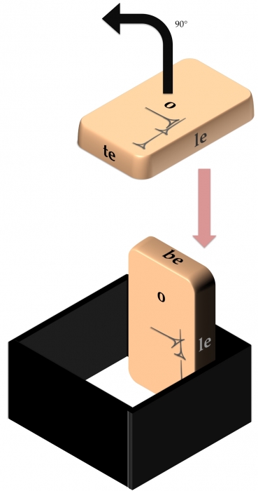
Fig. 3, Workflow after reverse
(8) Edges are difficult to scan due to the fact that tablets do not naturally rest on their edges and a tablet that is standing on its edge could be damaged if it falls over onto the surface of the scanner. So it is always best to prop up a tablet on its edge by some means available to you. Ideally, the supporting props employed should be black in color with a matte finish. These black props then disappear or can more easily be erased when producing the archival "fatcross" representation of tablets chosen by the CDLI (example). Under no circumstances, however, should a colored or textured background be allows to stand above the tablet so as to appear in the background of the tablet image (fig. 4).Fig. 4, Scanning the top edge with support
(9) Keep your eyes on the surface of the scanner to detect the accumulation of dust and fingerprints (as noted above, careful placement of a tablet on the surface of the scanner often requires touching the surface of the scanner with the fingertips, so expect to clean up a lot of fingerprint smudges). Clear any tablets or props off the surface of the scanner, blow any dust or other particles off the surface and clean off any remaining fingerprints or smudges with a piece of lint-free cloth.
(10) Once the tablets are returned to storage and the scanner has been cleaned, be sure to make two copies of the images produced and store them in two distinct locations. CDLI maintains an image archive that has long-term backup support through its partnership with the University of Pennsylvania and the German Max Planck Society, thus ensuring that archival images will be available to future generations. CDLI staff members are happy to produce a single archival image from each set of six surface images and to adjust the appearance of the archival image so that the tablet is easier to read. These services are all available free of charge.
Larger collections of cuneiform documents require a more efficient and less time-consuming method to image texts. Multiple scanning is a reliable and - with some experience - quick method to image more efficiently. Steps (1)-(3) for this method are of course identical to the afore-mentioned workflow.
(4) Place several cuneiform documents starting with the obverse on the surface of the scanner. It is your own judgment about the amount of documents you want to scan at a time without causing any problems in the file-naming process. Fig. 5 shows the scanning of six tablets at a time. It is important to note that the tablets should not be positioned to far to the borders of the scanner glass, since that might cause problems in the perspective of the respective sides. IMPORTANT: Place the tablet in the mirrored order on the surface, i.e., if you want to scan three tablets in one line, then place the first tablet on the right side and not on the left, as demonstrated in fig. 5.
 Fig. 5, Sequence of tablets from 1 to 6
(For Image Capture:) Produce an overview scan and select each tablet in the correct sequence. In the example given in fig. 5 you would start on the left upper corner. With all tablets selected you next have to choose a filename. The software does not allow for assigning a certain filename to each selection. Therefore a common denominator needs to be chosen. For instance, if you have an array of tablets Ashm 1924-0782, Ashm 1924-0783, Ashm 1924-0784, etc. you can choose a filename "Ashm1924-078_o" for the obverse(s) and change the filenames later in the respective directory. Important is to keep the sequence of the tablets for each side!
After scanning obverses and reverses remove the tablets (as they are) from the scanner surface and put them in the original sequence on a soft surface next to the scanner onto the respective labels (or bags), in order to keep the sequence visible. CDLI staff uses for scanning mission a so-called tablet-box, which serves as support for several boxes. Such frames can support the smaller and medium-sized tablets while scanning the edges (fig. 6)
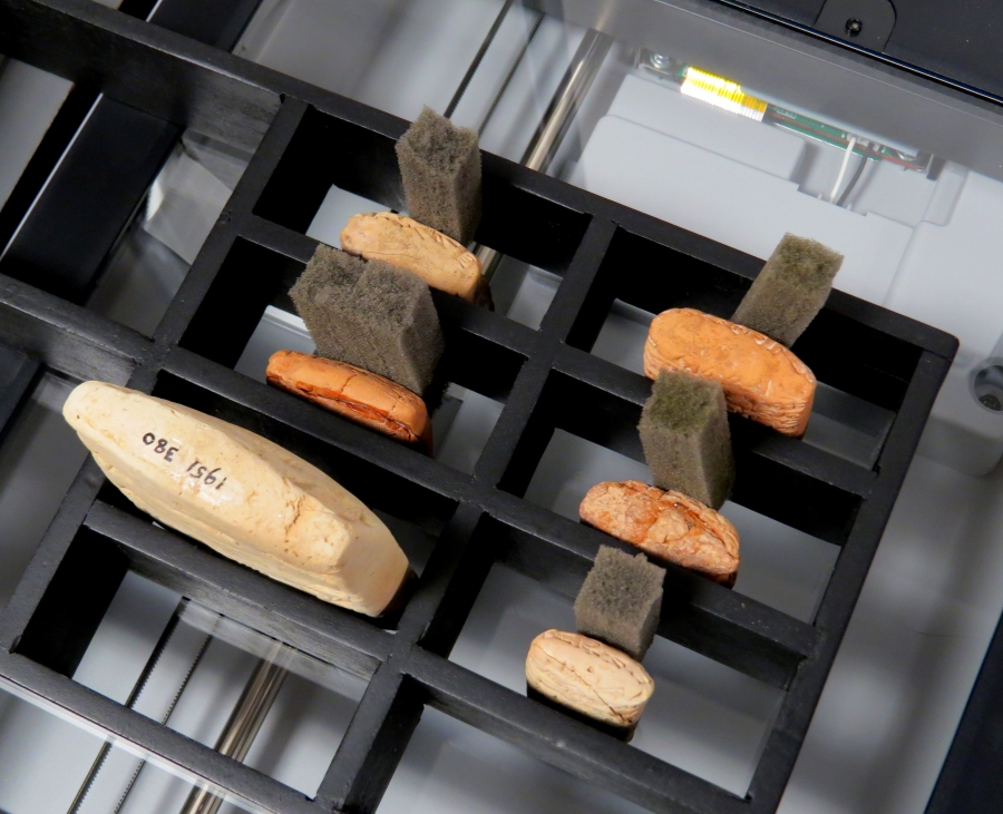 Fig. 6, Scanning the edges of tablets 1 to 6
In order to scan the top edges it is easiest to just flip the tablet up at the nearest edge seen from the operator.
Computing and scanning hardware should be the same as for scanning tablets, save that it is not as important to have a deep-bed scanner. There is also no need for a dark room.
The great majority of scanned images are of published autographs (line drawings of texts produced by hand). These should be scanned as an 24 bit RGB image (equivalently, RGB with 8-bits per channel), at a resolution of 150 dpi unless the drawing has particularly fine lines, in which case it should be scanned at 300 dpi resolution. It is best to save even black and white drawings under the RGB format because grayscale images do not preserve well when converting from TIFF to other formats like JPEG.
Color or black and white prints should be scanned at 300 dpi, 24 bit RGB. 'Make sure a descreening filter is on to prevent moire patterns from forming on the image.' It also helps to use an unsharp mask filter to improve contrast, although the image can be passed through this filter during the editing stage.
Photographs should be scanned at 300 dpi, 24 bit RGB, although higher scan resolution may be called for. If the scanner has an option for scanning glossy media, use that here. As with prints, use an unsharp mask filter now or save it for the editing stage.
Here is a summary of the scanning settings for book images:
Autograph Color and B&W Prints Color Photograph Image Type 24 bit RGB 24 bit RGB 24 bit RGB Descreening Off On On Scan resolution 150 dpi 300 dpi 300+ dpi
When scanning large volumes of photos or drawings (for instance, the contents of an entire anthology), following a few simple pointers will vastly simply later image processing.
Always orient the pictures the same way on the scanner, preferably so that the resulting images appear right side up on the computer screen. Try to position the pictures in the same place on the scanner, for instance, the lower right corner, so that it is easier to cut and paste images later, or even write macros which can do so automatically.
Unless it damages the book binding, make sure the book face is pressed as far down onto the scanner bed as possible, to prevent blurring of the picture near the center crease.
The camera domes developed and built at the University of Southampton, Electronics and Computer Science Department (ECS), produce 76 images, which correspond to the same number of daylight LEDs attached to the inner side of the dome. The capture software (RTIacquire) produces automatically the infrastructure for each object. If fully acquired by this imaging technology, a cuneiform tablet results into six directories each representing one face of the tablet (be, le, o, r, re, te). Each of these directories has the subsequent elements:
assembly-files camsettings.txt finished-files jpeg-exports original-captures The text file (camsettings.txt) contains all information about the camera settings for the capture process, but also eventual cropping, which has been enabled before initiating the capture process. These crops are being used for the processing software (builder); they crops need to be manually set using the RTI-builder!
The captures taken by the camera are automatically transferred to the folder "original-captures". While processing the images to a ptm-file these original-captures are duplicated and copied into the folder jpeg-exports. When shooting with RAW, the captures are converted to jpegs and copied there as well. After processing the final result (output.ptm) can be found in the folder "finished-files". Last but not least, the directory "assembly-files" contains a text file (capture.lp), which lists the X, Y, and Z coordinates of all 76 LEDs.
When preparing files for upload and backup, it is important to note that the above file-structure should be used for each side of the captured object. In order to avoid the usage of too much storage-space the content of "jpeg-exports" should be deleted before upload.
Here are information on capturing RTI images with the camera dome http://cdli.ucla.edu/pubs/cdln/php/single.php?id=54 Here are samples of RTI images of cuneiform texts and cylinder seals http://cdli.ucla.edu/?q=rti-images Processing RTI captures There are several ways to process images taken by the camera dome to an output file (*.ptm). The easiest way is to use the "builder". Upon opening there appears a small window. By pressing on the button "Build" the respective face of a captured artefact needs to be chosen. The user needs to select the main folder itself and not its sub-directories. Depending on the computer memory the processing takes about 2-5 minutes, whose completion is indicated by a dialogue "Fitting completed". In contrast to the RTIbuilder offered by Cultural Heritage Imaging, the fitting software takes all necessary steps itself. It copies the images in the directory "original-captures" and creates a duplicate in "jpeg-exports". After that the ptm-fitter is used in combination with the coordinates of each light source saved in "generic.lp". The 76 light positions (lp) represent the coordinates on the X, Y, and Z axes and are derived from the original calibration of the camera dome. (This calibration is done by placing a glossy ball (e.g., a red or black snooker ball) in the dome reflecting the various lights. Due to the reflections on the glossy sphere the location of the light source within the hemispheric camera dome can be extrapolated. A similar approach is achieved using highlight RTI and therefore an ever changing set of light positions within each capture.) During the building process the lp-file is copied into the folder "assembly-files" and renamed: capture.lp.
Until the CDLN are back online, see a PDF of for a description of Klaus Wagensonner's method https://www.academia.edu/6997535/Digitizing_in_the_round. This section will be updated based on recent improvements both of hardware and workflow.
In order to easily edit digital images it is important to have a computer with sufficient processing power as well as a reasonably sophisticated image editing program, such as Adobe Photoshop. CDLI uses Photoshop to prepare its images, and this is the program that will be cited in following examples. For basic Photoshop commands, consult the manual compiled by the West Semitic Research Project here. A Photoshop actions set used by CDLI staff to batch multiple files, and to facilitate individual image processing, is available here. Place the file "cdli actions.atn" in your "Photoshop Actions" folder, and load it to your actions palette.
Before delving into actual editing, it is important to have a clear method for saving and organizing images. Original scanned data should be kept in a separate folder from processed images, in a platform indepedent format such as TIFF. These original images are often called archival images because they form the backbone of any digital archive. Processed images should be placed in a different, clearly marked folder. For instance, archival images from the Journal of Cuneiform Literature, Vol. 24 could be saved in a folder named "JCS 24 Raw" while the processed images could be saved in a folder named "JCS 24 Finished".
Likewise, be sure to give each processed image as descriptive and concise a filename as possible, for instance by using the museum number given to the tablet or the page. This is especially important if the image does not show any museum number or other identifier that would indicate where it came from.
CDLI requires that its archival images be in a 24 bit RGB format (hence 8-bit channel), even if the image is black and white.
The following workflow describes step-by-step, how to create the final representation of a tablet in the CDLI database based on images produced by a flatbed scanner.
Software: The software usually used for Fatcrossing is Adobe Photoshop, which is usually cheapest bought as part of the Adobe Creative Cloud Package with a student/university discount.

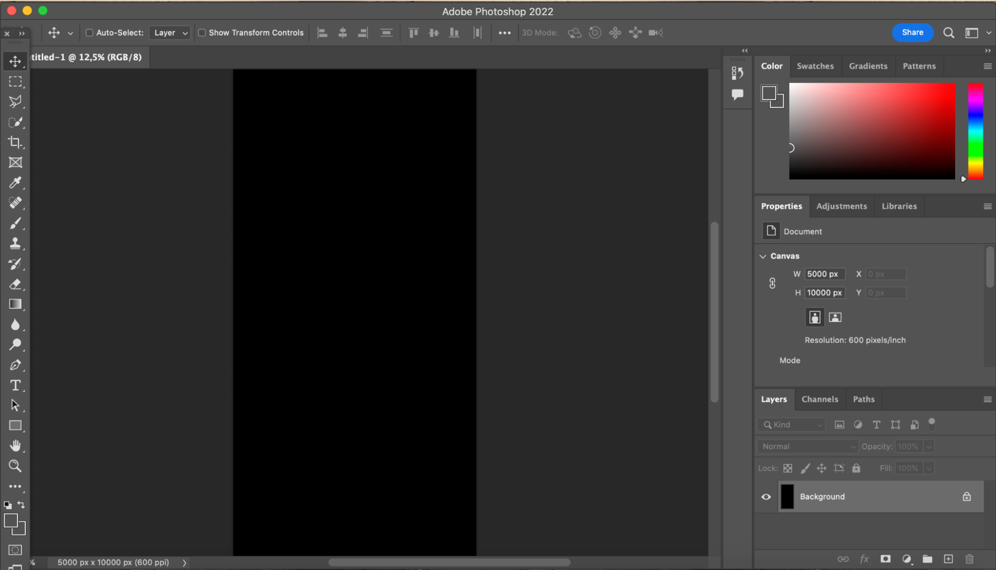
This will be the blank canvas on which the fatcross will be constructed.


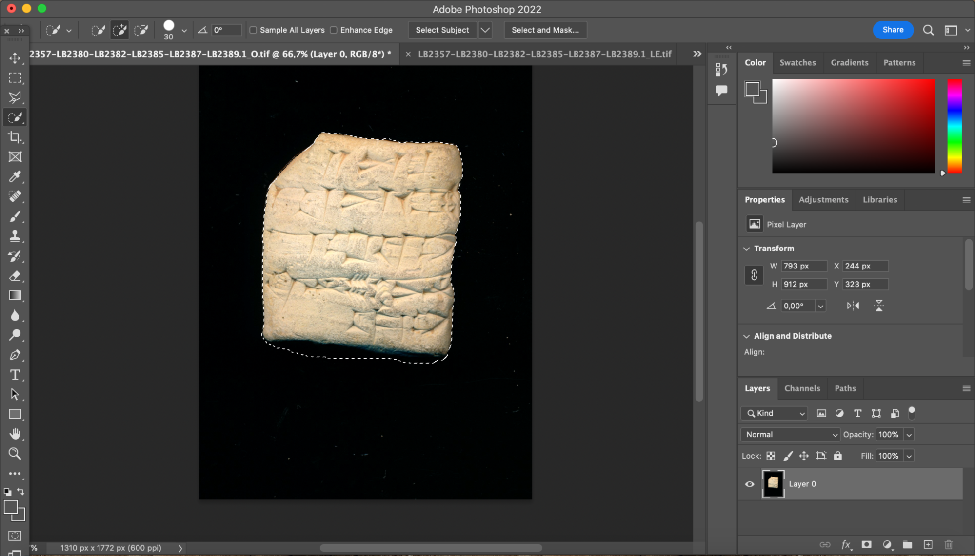


Repeat steps 4-7 for the other sides of the tablet (right edge, left edge, top edge, bottom edge, and reverse). If the raw images include several different tablets which have not been divided up into separate images, you will have to work out e.g. which right edge goes with which obverse etc. To help you can copy and paste the obverse onto the raw images of the other edges and see which tablet it lines up with and matches in size/shape etc.
Arrange the images of the individual fragments into the shape of the fatcross, leaving a small gap between each image. Make sure the images are in the right place and orientation as sometimes they are mistakenly scanned upside-down or given the wrong label. If possible, check any transliteration/line-drawing or other information available about the tablet on CDLI or elsewhere to make sure everything is where it should be. Make sure the separate images are lined up as well as possible so that e.g. the same wedge on two images is lined up. If you need to rotate any of the images to make them straight, use the free transform tool (edit>free transform; PC ctrl+T; Mac cmd+T) to rotate it, but be careful not to change the size of the image.


The goal here is to remove as much of the interfering background on the page while preserving crisp, unpixelated cuneiform drawings. We illustrate the clean up process with an image from 'LIH Vol. 1'.
As is often the case, the original drawing is on faded tan or semi-transparent paper
We first change the background color to white using the 'Replace Color' command under 'Image > Adjustments'. Click the Eye Dropper Tool on the tan background and increase the brightness factor to %100. Additional background colors may need to be filtered out using the Eye Dropper+ Tool. Our intermediate image now looks like
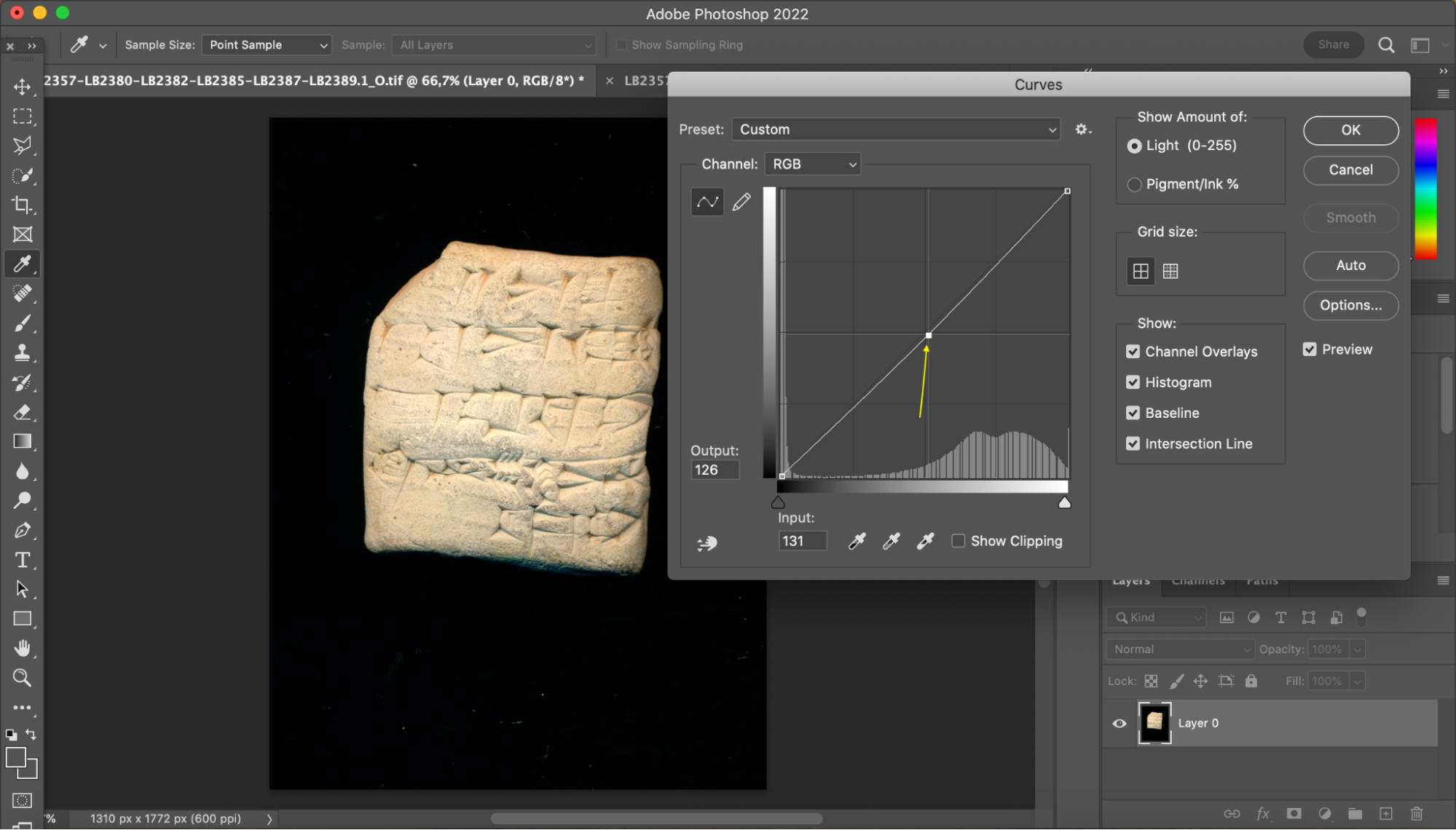
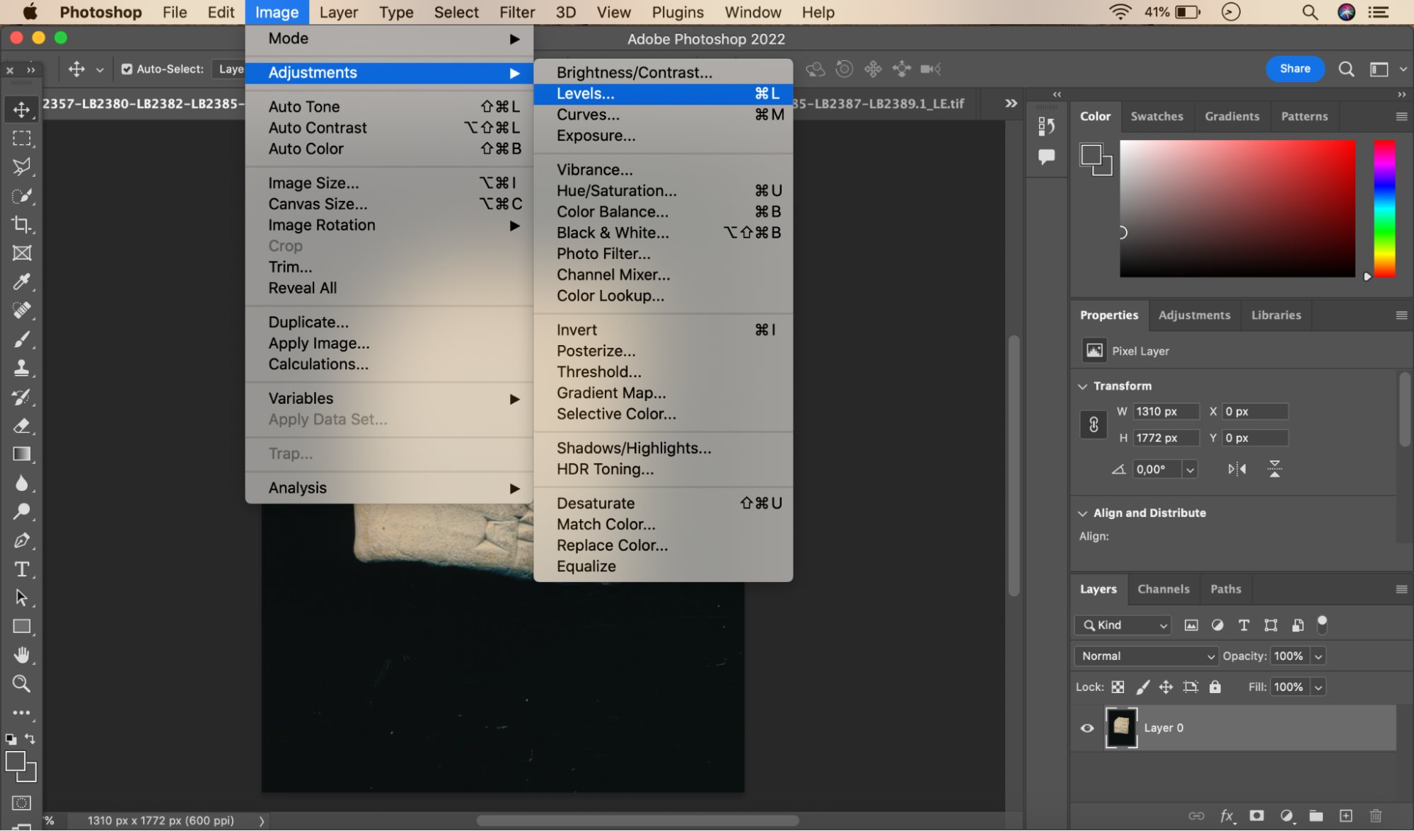
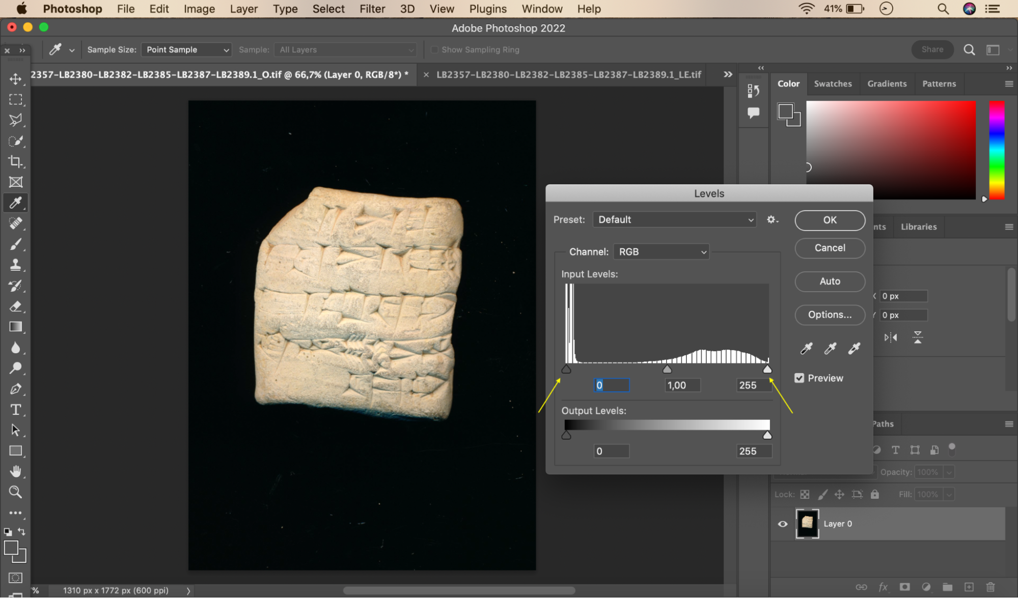
We then use the 'Desaturate' command under 'Image > Adjustments' to convert all remaining color to gray-scale. Then we fade out background lines and shadows by increasing the brightness factor, and bring out foreground lines by increasing the contrast factor. These variables are controlled using the option 'Image > Adjustments > Brightness/Contrast'. In general, CDLI has found that increasing the brightness contrast factors beyond about 20 lowers the quality of the image. For more subtle contrast in shading, you can edit the RGB histogram under 'Image > Adjustments > Levels…' or just let the computer edit it under the 'Image > Adjustments > Auto Levels…' command. You can also go to the 'Image > Adjustments > Curves…' command for more customized adjustments.
We then crop the image to cut out the surrounding text, and use the eraser to eliminate line numbers, smudges, and other errant lines. After adjusting the brightness and contrast a bit more, we end up with
Finally, we save the file under "038_l.tif" in the folder designated "LIH1 Done" to indicate it is text number 38 in volume 1 of Letters and Inscriptions of Hammurapi.
NB. When saving, make sure the file is in TIFF format and is uncompressed, with IBM byte order. Also, when arranging the image of a tablet with separate drawings for each side, be sure to follow standard CDLI conventions: reverse side placed underneath the obverse side; lateral or top side images placed surround the obverse; partial seal drawings can be placed under the reverse, but line art drawings of envelopes that belong to the same text are put in a seperate file called, in the instance above, "038_le.tif".
Processing Photos Editing photos requires greater subtlety because of the information density in the image. The same procedure as above is used to create a final image, although in this case more work may need to be done to clean up dust or scratches, and to improve color balance. We therefore describe a few useful clean-up techniques when working with photos.
'Unsharp Mask Filter'
If you have not already applied an unsharp mask filter to the image, do so now. You can also adjust the parameters for the filter to achieve better contrast. The three parameters used in Photoshop are Amount, Pixel Radius, and Threshold. For a more detailed description of these terms, see Wayne Fulton's Scantips site.
'Despeckle Filter' This filter smooths out spots that are surrounded by a sharply contrasting background, for instance, a speck of dust surrounded by total black. It works best when applied to an area where the dust spots stand out more clearly than anything else in the image.
'Dust and Scratches Filter' Similar to the Despeckle Filter, save that you can adjust the pixel radius and threshold of the filter.
Edit File Handling All archival and processed files are stored at UCLA with a full backup at the University of Oxford.
This page explains how CDLI creates, processes, stores and display digital images. For an extensive overview of the thoughts that have been put in the methods developed to capture and store image data representing cuneiform artifacts, please read "Looking both forward and back: imaging cuneiform" by Jacob L Dahl, Hendrik Hameeuw and Klaus Wagensonner. https://cdli.ucla.edu/pubs/cdlp/cdlp0014_20190319.pdf
Original files used to create the archival images associated to artifacts are generally stored in case we would need to reconstruct or correct archival images. This comprises generally of original flatbed scanner images captured in collections, and scanned version of paper published volumed which contain lineart drawings. We also preserve original files for other formats of visual assets but we do not systematically offer storage for these other formats, due to space constraints.
The name of these original files will follow the naming practices used at the time of data collection. A text file can be added in the folder, explaining how the files were named.
Anyone interested in storing such images at CDLI should write to us at cdli@ames.ox.ac.uk
Archival images are the core images from which all images are derived. They are based on processed raw images. In the case of tablet photos, this involves assembling a tight fatcross, cleaning the background and other adjustement tasks which are outlined in the "Creating fatcrosses" section below.
All image files should start with the P number of the artifact. We use a few codes to be placed before the extension to help with sorting the type of image the files contain. The codes are as such:
CDLI can accomodate only for one image of each type.
In order to put the archival fatcrosses in storage, and to derive web version of images, the files must first be renamed. Various tools can be used to arrive to the desired result, one of these methods is described below.
In the folder that contains the images to rename on a Mac computer: remove the excess information from the file name.
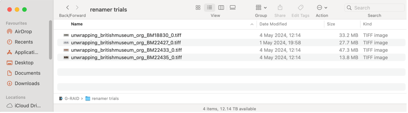
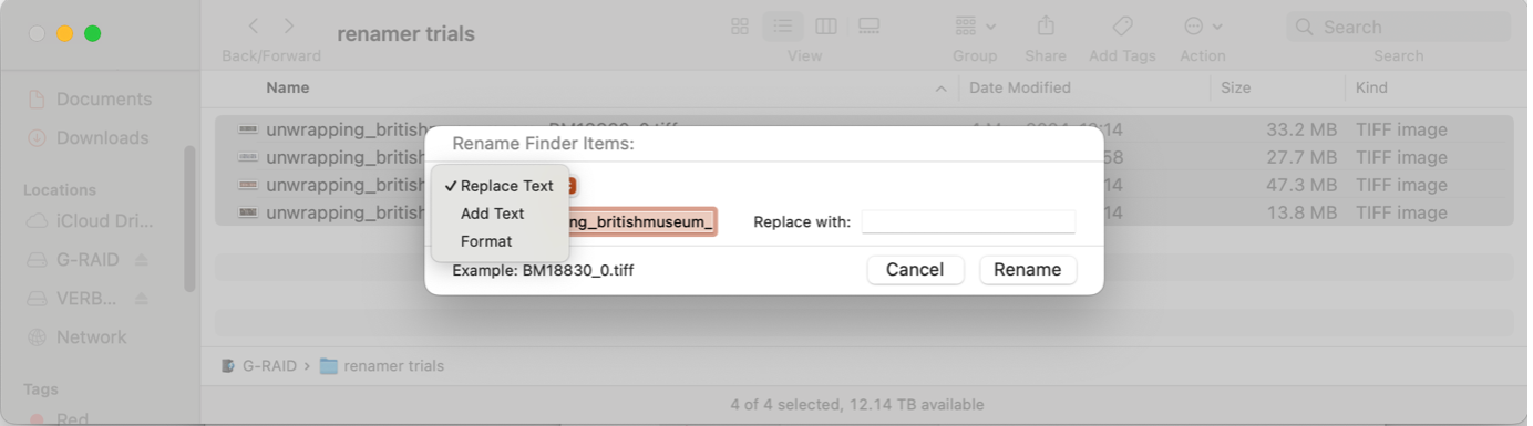
You can do this by selecting all (cmd + a), then right clicking on the list, and selecting "rename".

Make sure the drop-down menu is selected to replace text
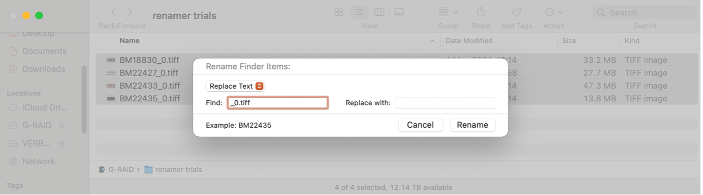
You will be left with just the museum number.tiff

Install and open the renamer app (download from https://renamer.com/)
You will see a screen that looks like this
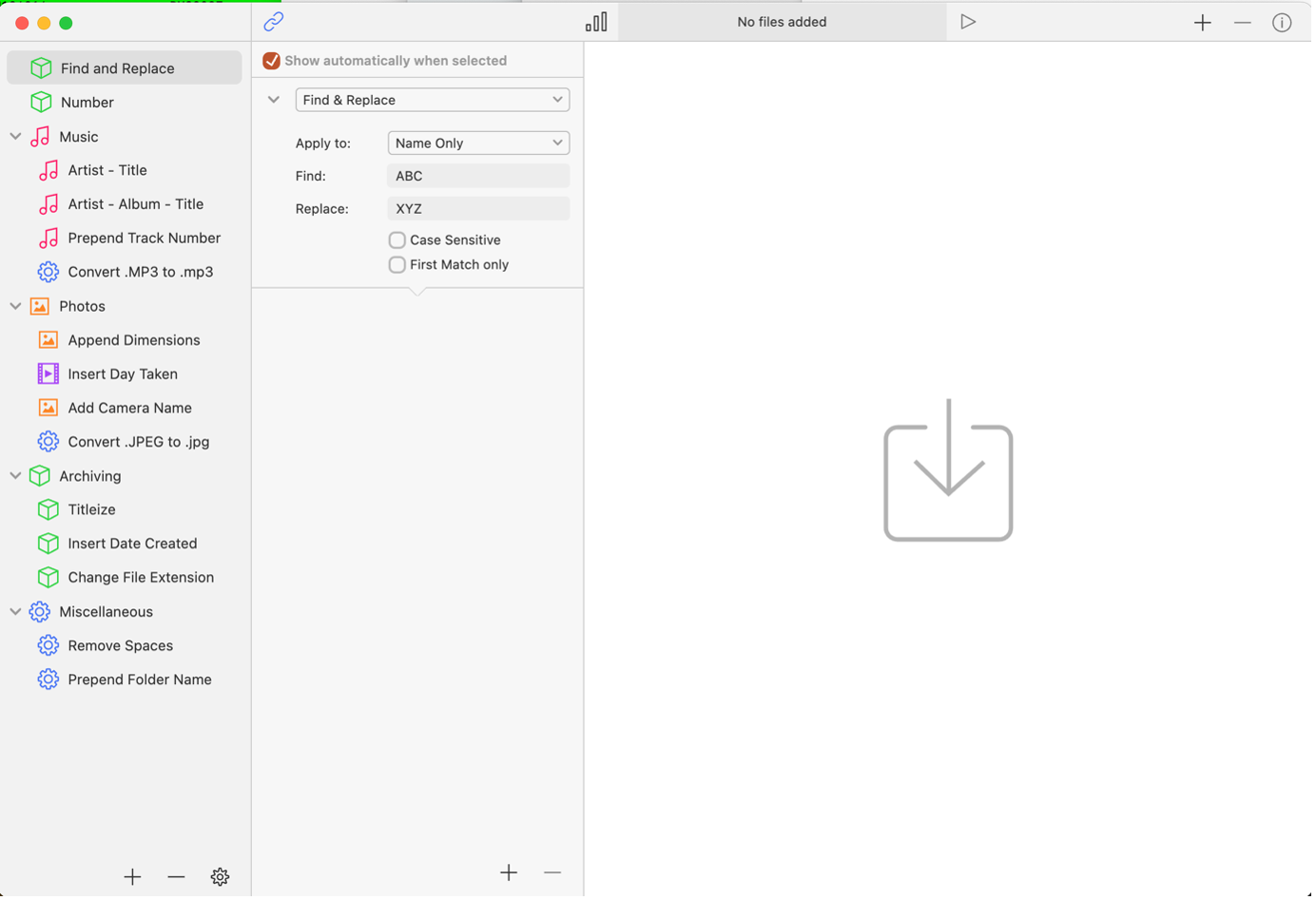
Select the files from your images folder to rename. This can be done in a few ways:
After adding the images, the Renamer interface will change. There will be two new components on screen. The current name and new name columns.
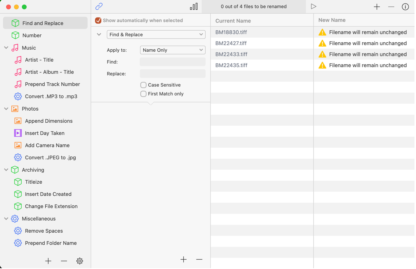
From here click on the drop-down menu currently labelled as Find & Replace and select rename from spreadsheet.
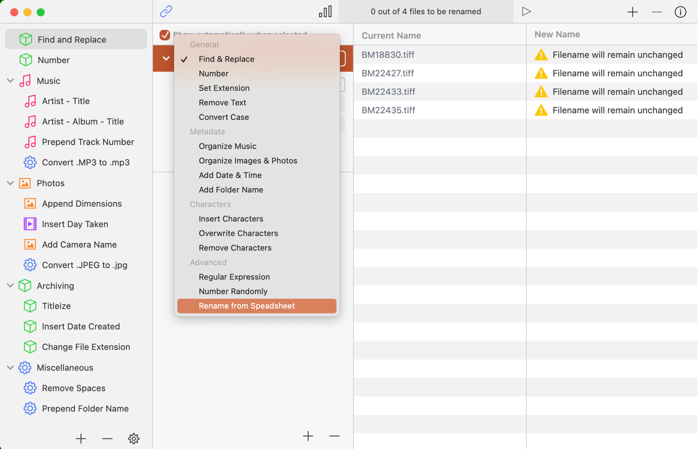
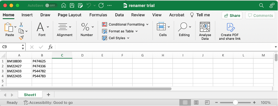
Click the choose file option and select your cvs file with the list of your museum numbers next to your P numbers. This will automatically apply, and you can see an example of what the renamed files look like.
NB: if you have headers on your cvs document make sure to select the skip headers check box before choosing the spread sheet.
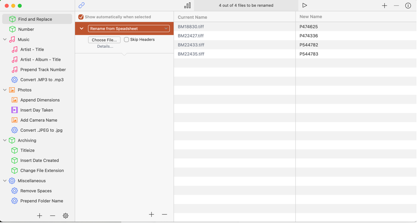
The last step is selecting the apply button (looks like a "Play" triangle) which is located at the top right of the screen to the left of the + and – buttons.
This will rename all of your files.
Web images are processed version of our archival stock in formats optimized for web viewing.
All our images are shared from the CDLI digital library directory at https://cdli.ucla.edu/dl/. The tree structure of the digital library looks like follows:
├── lineart
│ └── Pxxxxxx_l.jpg
│ └── Pxxxxxx_ld.jpg
│ └── Pxxxxxx_ls.jpg
├── pdf
│ └── Pxxxxxx.pdf
├── photo
│ └── Pxxxxxx.jpg
│ └── Pxxxxxx_d.jpg
│ └── Pxxxxxx_e.jpg
├── ptm
│ └── Pxxxxxx_o
│ └── x_x.jpg
│ └── Pxxxxxx_r
│ └── Pxxxxxx_x(x(x))
├── svg
├── tn_lineart
│ └── Pxxxxxx_l.jpg
│ └── Pxxxxxx_ld.jpg
│ └── Pxxxxxx_ls.jpg
├── tn_photo
│ └── Pxxxxxx.jpg
│ └── Pxxxxxx_d.jpg
│ └── Pxxxxxx_e.jpg